There are numerous DIY projects a homeowner can attempt that look deceptively straightforward at first glance. Even for experienced DIYers and professionals familiar with these tasks, unforeseen hurdles and roadblocks tend to pop up in the most frustrating of places. Of all of these potential hair-pullers, installing three-way switches is one of them.
Let’s see if we can’t simplify them a little bit, and make them easier to master.
First Thing’s First: How Is a Three-Way Switch Different?
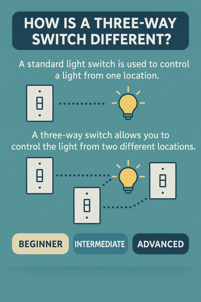
At the risk of stating the obvious, a properly installed three-way switch is not the same as a standard light switch. While the Internet Age has made us accustomed to a lot of conveniences that depend on digital implementation. Prior to that, finding ways to make things happen required more practical and tangible designs.
So while you could conceivably use smart devices and IoT to control a light from multiple places and interfaces, a dedicated switch in the wall involves a few very specific additional steps.
We don’t know your personal level of experience and familiarity with electrical systems, so we’ve broken down the following explanation into different brackets. Feel free to choose the one that meets you where you’re at.
“I’ve Replaced a Light Bulb Before…Does That Count?”
Everyone starts somewhere, and it’s never at “expert.” All of us were where you are now, at some point. So don’t be embarrassed if this all feels very intimidating.
That being said, you’ll want to understand the basics to make sure you do this right, and to ensure the rest of this makes any sense.
When done properly, the power cables that have been run through your walls have three wires: a black, a white, and a bare copper wire. The black is the “supply.” Also referred to as “hot,” “positive,” or “live,” this is where incoming electricity comes from.
The white is the “return.” When connected, electrons are flowing through this line as well, but when the circuit is open, no power is being supplied to the white wire, so it lacks a charge. As for the bare wire, that’s the “ground,” and it’s a safety mechanism.
Normally, when installing a switch, outlet, light, or anything else, you would match black to black, white to white, and connect the bare copper wires to provide a grounding connection. If instead you’re installing a three-way switch though, there’s a critical fourth wire: the traveler.
“I Already Own One of Those Beeper Pen…Thingies”
Electrical systems function based on circuits. When you flip a standard light switch, you’re completing a circuit, allowing electricity to flow to the lightbulb. When you toggle it off, it opens (disconnects) the circuit, interrupting the flow, and turning off the light.
Power only flows when the circuit is connected, and most on/off switches disconnect some or all of a circuit to power it down. Odds are, you’ve learned some of this already, even if just when you had to reset a breaker.
“Maybe I Should Have Been an Electrician…”
If you’ve replaced or installed a few things like this before, this might seem old hat by now. If that was all there was to it, though, three-way switches wouldn’t exist. Both switches would have to be set to “on” to connect the circuit, and flipping either off would leave the lights without power. That’s an implementation that’s decidedly less convenient than even a standard, single-pole switch.
Three-ways answer this paradox by connecting the two switches via “traveler” wires. This requires a different setup and specialized materials in order to function as intended. The switches must be three-way switches, and they must be properly connected by travelers.
In short, you’ll either need to wire in the correct switches using an existing three-wire cable, or you’ll need to add a traveler connection yourself. Otherwise, your three-way switch becomes a “put both into the correct position” switch.
Two Questions When Installing a Three-Way Switch
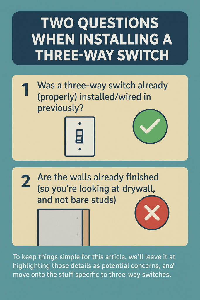
Now that we’ve gotten some of the basics out of the way, we need to discuss the two primary circumstances that impact how challenging this is going to be:
- Was a three-way switch already (properly) installed/wired in previously?
- Are the walls already finished (so you’re looking at drywall, and not bare studs)?
If you’re lucky, all you’re doing is upgrading, updating, or replacing switches in an otherwise functional circuit. If you’re unlucky, you’re dealing with an incorrect installation, and it’s already covered by the finish work. For those souls that are faced with that reality, we salute you.
What tools and supplies you’ll need, the level of work involved, and how many times you’ll have to mutter four-letter words as you drive back to the hardware store yet again will all largely depend on the answers to the two questions above.
To keep things simple for this article, we’ll leave it at highlighting those details as potential concerns, and move onto the stuff specific to three-way switches.
How to Configure a Three-Way Switch
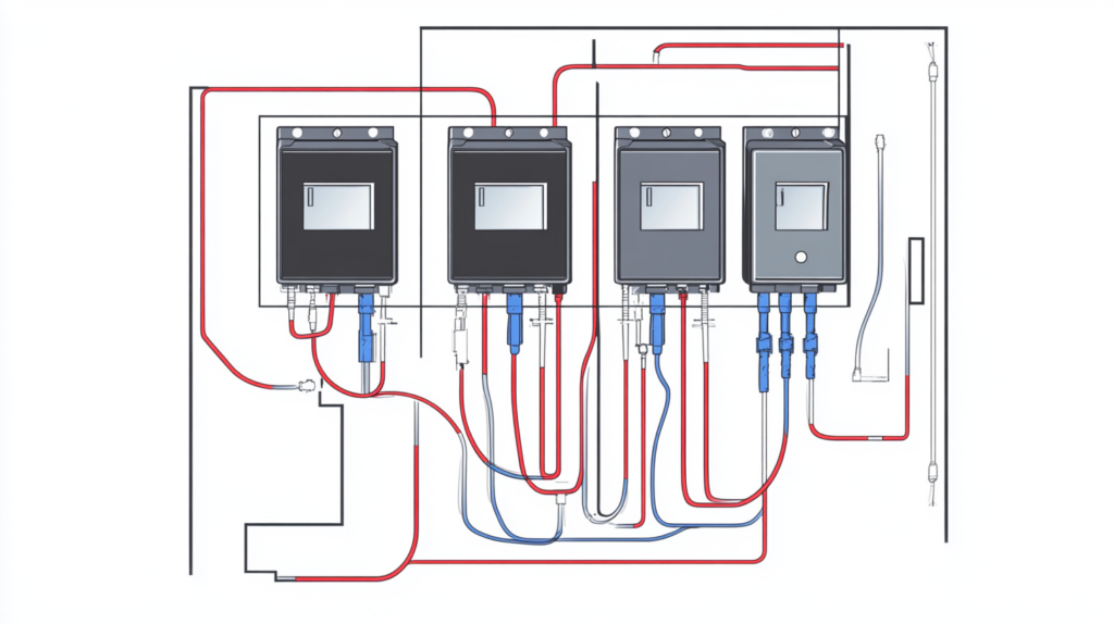
There is, in fact, more than one way to arrange a three-way setup. In fact, there are at least three, with each defined by the positions of the light (or lights) and switches relative to each other, and the incoming power source.
In the interest of clarity, we’ll use letter designations for each of the main components:
- “A”—The incoming cable (a two-wire with ground), which is connected to the power source
- “B”—The traveler cable (a three-wire with ground)
- “C”—The first three-way switch, which is always connected to the incoming power
- “D”—The second three-way switch
- “E”—The light (or lights, if there are multiple, but we’ll save that level of complexity for another time)
The optimal configuration is as follows:
Incoming power (A) connects to the first switch (C); the traveler cable (B) connects C to the second switch (D); and the second switch is then connected to the light (E).
This can also be configured with the light (E) in the middle and the switches (C) and (D) on either side, or with D connected only to C, and C connected to both D and E.
If those additional setups sound complicated, it’s because they are, and most experienced professionals will opt for the more streamlined, straightforward, and (in some cases) compliant configuration described in the first example.
We mention other versions here primarily because, if you’re trying to fix a setup that’s not working like it should…there’s a chance it’s one of those (and it wasn’t assembled correctly). In which case, you’ll either need some idea of what you’re looking at (hence the explanation), or you’ll need to call an expert.
How to Wire a Three-Way Switch
Now, even if you’ve got the right parts, and you’ve picked (or are lucky enough to already have in place) the simplest arrangement, you can still goof this up if you don’t plug the right wires into the right places.
In a normal, single-pole switch, you match black to black, white to white, ground to ground. Attach the incoming power cable to the appropriate terminals, and then attach the outgoing wires (that run to the light) to the other set of matching terminals on the switch. Done correctly, the switch will energize the light when flipped up, and disconnect it when flipped down.
For a three-way, you have to do it differently. Using our optimal configuration as an example, you’ll connect the incoming power (black wire from A) to the first switch (that’s C for folks keeping score at home). You’ll connect the ground as usual. But you don’t connect the white wire from A to the matching terminal on C.
Instead, the traveler cable (B) should have a black, a red and a ground. You’ll connect the ground to the same pairing between A and C. For the black and the red, you’ll connect each to the corresponding terminals on switch C. If you can’t find the right terminals, double and triple check.
If you still can’t find it, you may have a standard, single-pole switch, and you’ll need to swap it for a three-way switch. Without it, the terminals won’t match, and it won’t function the way you’re hoping.
Once you’ve sorted out connecting A to C, and C to B, it’s time to move over to switch D. Here, you’ll connect the black and red to the appropriate traveler terminals on this second switch. You’ll connect the ground to the bare copper wire from B, and the bare copper wire from the light (E).
So far so good? Great; we’re in the home stretch, now. Next, connect the black wire from the light (E) to the power terminal on the second switch (D), just like you connected the power from A to the first switch (C).
Finally, you’ll connect the white wire from E to the white wire on the traveler cable (B), and then connect the other end of the white traveler wire to the white wire on A.
In summary:
- Black A to power terminal on C
- Ground A to ground B1 and ground C
- Black traveler terminal C to black traveler B1
- Red traveler terminal C to red traveler B1
- Black traveler B2 to black traveler terminal D
- Red traveler B2 to Red traveler terminal D
- Ground B2 to ground D and ground E
- Black E to power terminal on D
- White E to white traveler B2
- White traveler B1 to White A
Once you’ve finished (and, likely, gone back at least twice to swap wires to where they should be), you’re ready to flip the breaker back on, and test the circuit. Barring any frustrating hiccups, you should be able to operate the light from either switch, independent of the other one.
There are four possible combinations of positions between the two switches: both up, both down, up/down, and down/up. When working properly, the position won’t actually matter for either switch, just how many times a switch has been flipped (e.g. if it’s off, flip either once, and it’s on; flip either once more, and it’s off again).
You’ll know something’s amiss if only one of the four combinations turns the light on, or only one turns the light off. Or, well, if the switches otherwise behave in any way other than what makes immediate, intuitive sense.
That’s it. That’s the whole thing. Hopefully, it was as simple as we made it sound, and you’re both finished with the project and happy with the results.
Tagging Out
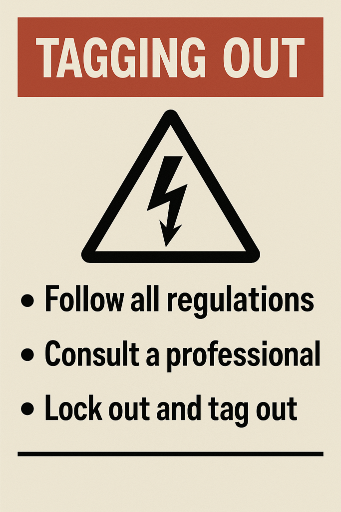
We’ll conclude our discussion here by highlighting some important reminders—reminders that might seem obvious to some, but may be easier to overlook than expected.
Electrical installations are heavily regulated in most places, with many of those regulations consistent across nearby regions (states/provinces/etc.). Failing to follow the guidelines and regulations has two downsides: one, it’s technically illegal, and that tends to come with penalties. Two, it’s dangerous; the regulations are nearly all centered around safety concerns, like fire risks. So do your research, and make sure you’re following the rules.
When in doubt, consult a professional. Again, electrical systems are dangerous, and if you’ve found “odd” or “creative” installations elsewhere in your home, you can probably expect to see similar “freestyling” even in the electrical work. This is one area where deferring to the certified expertise of someone who is…well, a certified expert, is not just the safe answer. It’s the smart answer.
Finally, be safe. We think of standard 120 volt circuits as being low risk, and they are, comparatively speaking. But they’re not no risk. So take the appropriate and recommended precautions, including locking out/tagging out, using protection and current detectors, having someone on hand in case of an emergency, and so on.
Other than that, have fun making connections. Check us out at Homeowner.org for more on home warranties, home improvement, and home remodeling. We’d love to help you optimize your experience as a homeowner!